< Return to Engineering Projects
This project was created during the 2023 Spring Semester for ES227: Medical Device Design.
Project partners were Olisaneme Okonkwo, Clayton Donhauser, and Nate DeLucca.


This class worked by pairing you up with a client that had some kind of need for a new technology. In our case, we were paired with the head of a Taekwondo Studio, and the need was for a new kind of impact measuring technology for the Taekwondo scoring system.
Taekwondo is a very old martial arts form that was only came up with a standardized scoring system for the sport in the late 1990s to early 200s, in order for it to become an official Olympic sport. The scoring methods have evolved over time, and has valued different fighting aspects differently over time. For example, from the 1980s to the 1990s, scoring was done by multiple judges watching the same fight, and was based on ‘match domination’, which was subjective and made players fight with moves that would make them appear more powerful. In the mid 1990s, the sport started using electric scoring systems, with points being awarded in real time during the fight. This encourages athletes to do many moves in combination to raise the chance of being awarded a point.
The current style of Taekwondo, according to our stakeholders, deviated from both of these styles. It is no longer really focused on technique or power, but instead on taking advantage of the electric bodyguards integrated with impact sensors that are currently used to award points. The system is shown below, where the yellow dots on the sensor socks are magnets used to trigger impacts, since a point is only awarded if a blow is landed with a legal body part, such as hands or feet.

The current scoring system has led athletes to attempt to land blows with smaller surface area, usually with the heels of their feet. Many feel that this has caused Taekwondo to deviate from its original form and values.
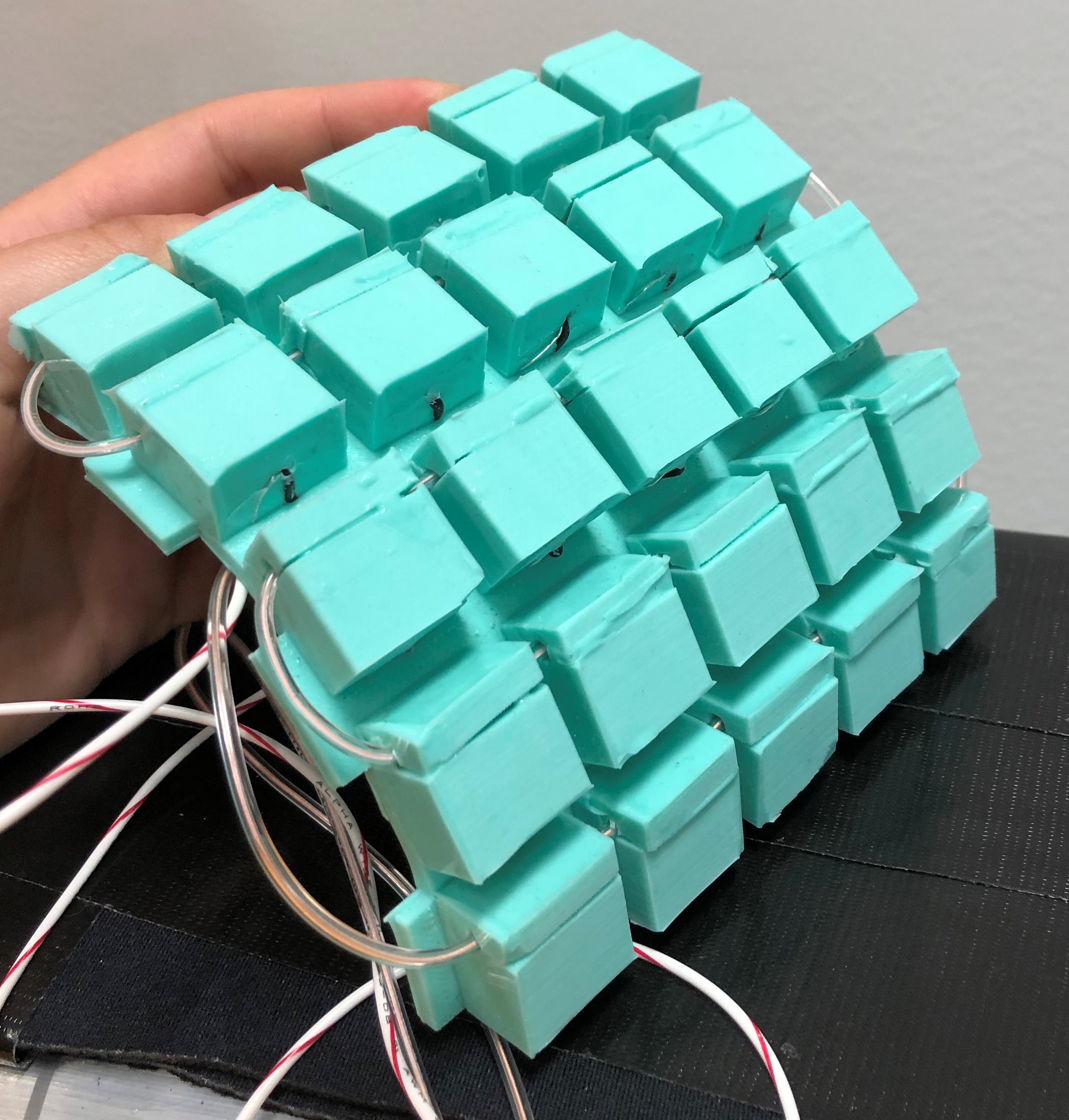
My group attempted to design a new force sensor. We decided to go with a concept called the ‘optical tunnel unit’ (right), which would be combined into a ‘mango unit’ (below).


We decided to call it a mango because of how it resembled a sliced mango (right).

The optical tunnel unit worked by taking advantage of the material properties of the cube, which would be made out of silicon. With a light source – the EL wire – and a tunnel between it and a photoresistor, when impact was made on a unit, the force of the impact could be calculated from the deformation of the tunnel.
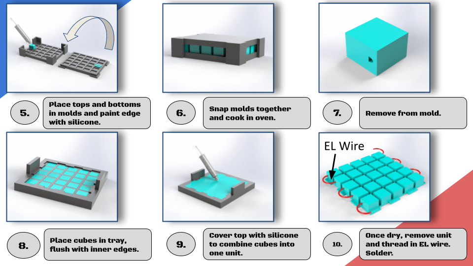
The manufacturing process of a mango involved a multi-step casting process, shown on the right. These slides are from our final presentation.

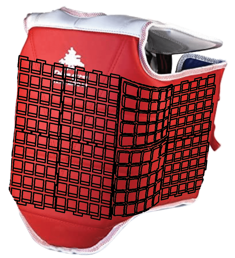
Mango units were made to be peiced together inside of the protected equipment, as shown on the left.
Designing the mango also meant designing the circuitry for the photoresistors, and this circuitry had to make sense for the force measurements we wanted to be taking. We wanted to reduce the amount of wires inside the mango as much as possible, as they could be susceptible to repeated impacts (except for the EL wire, that would be fine). To do this, we wired the resistors in series, and implemented a voltage divider so that the relationship between force and voltage would be directly proportional.
Our full circuit diagram and the equations governing force measurement, as well as abaqus simulations of the optical unit are in the final paper attached below.
