A virtual reality environment built to let the user explore a microchip in super-size.
This project was worked on from June 1 to August 12, 2022. It was build for Dr. Gage Hill’s Nano-Design Lab at Harvard.
Microchips are really small units of electrical logic gates that are put together to make a function. They exist in virtually every electrical appliance, and their use is becoming more prevalent as technology grows.
I was not working on microchips themselves, but rather an issue with their display method. Below is a build schematic for a very simple microchip – a NOR gate. Its size is 80 square micrometers.
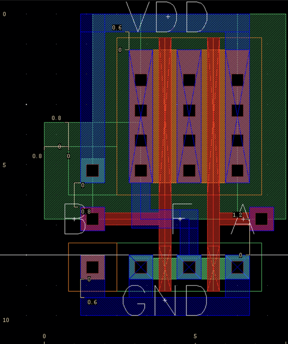
It is very difficult to decipher what this chip looks like in real life, and even once it is made into a physical object it is so small that you can’t see it without a microscope.
When electrical engineering students first learn about these, it is difficult for them to visualize how these chips are built and how they appear.
Dr. Gage Hill’s lab designs and build microchips, and he also teaches electrical engineering. I was hired to build a virtual reality game that would allow the user to upload a microchip schematic, and then enter the environment to see it built in a super-sized scale and interact with it. This would be an excellent teaching tool, and would also allow students to translate the difficult build schematics on their computer to the more intuitive 3D build.
I started by getting familiar with the game development platform, Unity, and with virtual reality itself. This involved learning how to make my virtual self be able to move, interact with objects, fly, and collide with objects, and took about two weeks of watching youtube tutorials for game development in Unity. I also had to familiarize myself with VR – I hadn’t played any VR games up until that point, so I played through free demos of games to learn which controls were the most intuitive for which actions. Then I was able to start thinking about how to load a microchip build schematic into the game.
Loading a schematic first involved that schematic being turned into a formatted text file of shapes, their sizes, colors, and locations, as well as their material labels and layer numbers. One of my electrical engineering coworkers wrote a python program to do this.
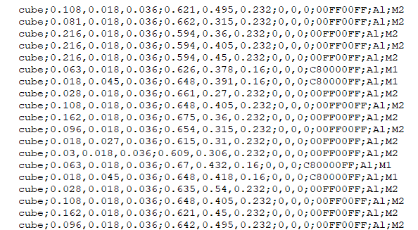
To the left is an example of this formatted list. In order of left to right, it reads:
shape of the object; dimensions x, y, z; location x, y, z;rotation around x, y, z;hexidecimal colorcode;material label;layer label
Unity allows the developer to write custom scripts in C#, so I wrote a script in the editor window that would allow the user to be a developer and load in their own schematic, orient it in the environment, update the game, and then play it as designed. This also involved figuring out Unity editor scripting practices and Unity GUI commands, so that the user would have to do the least amount of scripting possible.
The editor window script was called editorBuildEnvironment, and contained the code designing the GUI interface as well as all the code for building the microchip.
Other scripts written include:
- expanded_view
- This was attached to an in-game toggle and slider that when activated, controlled the distance between different layers of the microchip.
- menu_page
- This controller the user interface within the game – the interface allows the user to go into expanded view, select which layers are visible, or switch between microchips.
- player_controller
- Contains most of the code for character movement, including moving, jumping, and flying.
- SceneController
- This is attached to the buttons in the user interface that allows the user to select which environment they are looking at.
- user_interactions
- This contains the code that allows the user to open and close the user interface menu.
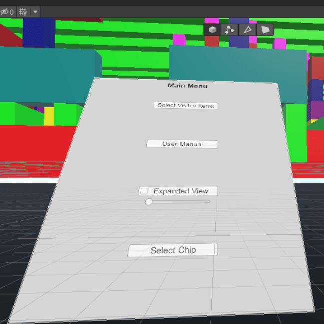
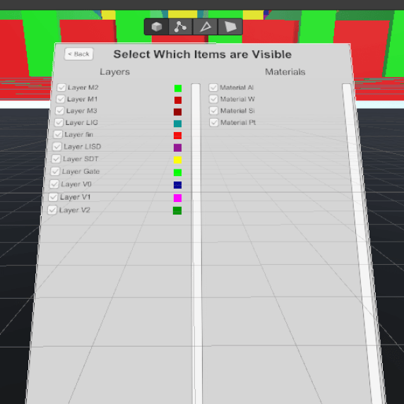
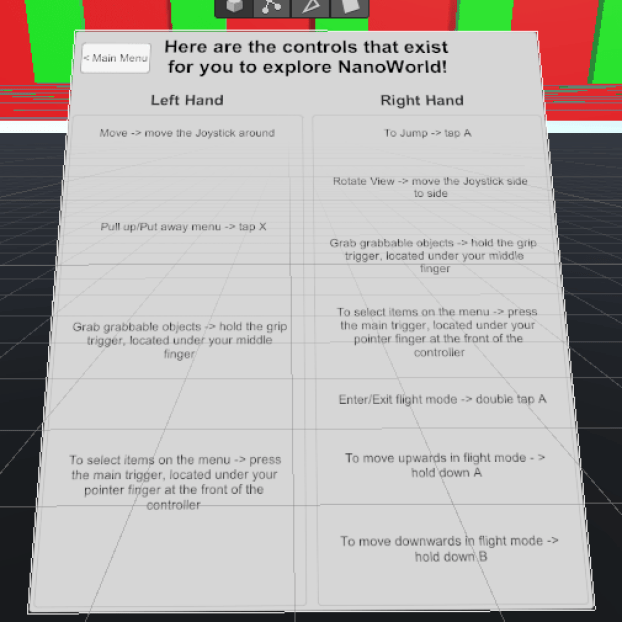
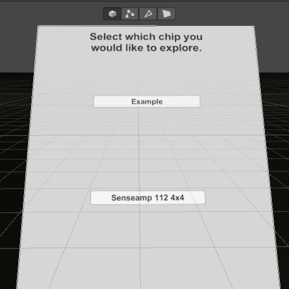
Below are images of what the in-game user interface looked like. It could be summoned or put away using the hand controllers of the VR equipment.
Below is an image of what a microchip looked like once it was loaded into the environment.

At this point, my work period ended and the game was playable and could be used. If I had more time, I would have tried to implement the following things:
- Add controller shapes for the hands.
- When I left, the hands were ‘visible’ by little rectangles set to where the controllers in real life were placed – if I could find files for the actual controllers, I could set those to the hand shape. This would help people who weren’t used to VR see which buttons were where.
- Edit the expanded view functionality so that it will move the user with the blocks.
- This was requested by Dr. Hills because users would get disoriented and lose track of which layer they wanted to look at when they expanded the layers. Implementing this would keep their relative location to the layers the same, and would make it easier for them to keep track of layers.
- Make a minimap!
- A minimap in a game is usually a small map in the corner of the screen that shows a character where they are in the environment, usually from a birds-eye view. Implementing this would allow the user to keep track of where they were in the microchip, and if the lab decided to upload multiple microchips to the environment it might assist them in traveling between the two.
- Explore the possibility of uploading multiple chips to the same environment.
- When I left, I had made the game so that there was only one chip per environment – if they wanted to upload multiple chips to one environment they could, but any controls like expanded view or layer selection would affect both chips. Would it be possible to select which chip they could control so that the user could change the chips separately?
